Modes and transmission in periodic slabs
Through a series of diagrams, the concept of anomalous transmission
induced by a nonrobust guided slab mode is explained. For
simplicity, the scalar Helmholtz equation in two dimensions is used.
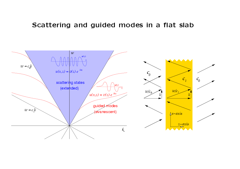
The diagram on the right depicts scattering of a plane wave by a
uniform flat slab. The frequency is ω and the wave vector in the
x-direction is k. The (free-space) speed of light in the
air is c=c0, and the (free-space) speed of light in the material of
the slab is c=c1. At frequency ω, the air supports
waves of wave number ω/c0, and therefore travelling
waves in the air must have k≤ω/c0, in other words,
(k,ω) must be above the light cone ω=c0k depicted in
the (k,ω)-plane in the diagram to the left.
The field u satisfies the Helmholtz
equation (∂xx + ∂yy)u + (ω/c)2u =
0. Since the structure is independent
of x, we can consider solutions of the form u(x,z) =
v(z)eikx. For each point (k,ω) above the light cone
ω=c0k, such solutions are constructed simply by
matching oscillatory functions v(z) across the air-slab interface.
The oscillations in the slab are tighter because
c1≤c0 (as suggested by the graph of v(z) in blue). These are the "scattering states",
or "extended states" of the air-slab structure.
The region between the cones ω=c0k and ω=c1k
(the latter is the light cone for a space filled with the material
composing the slab) is the (k,ω)-regime in which v(z) is
exponential in the air and oscillatory in the slab. In order that
the solution be bounded, it must decay as |z| tends to ∞. This
only happens on certain "dispersion relations", calculated again
by matching exponential functions in the air to oscillatory
functions in the slab and demanding that the growing components
vanish. These are indicated in red. Each point (k,ω) on any one of
these relations corresponds to a "guided mode" of the slab, whose
form is suggested by the graph of v(z) in red. They are
"evanescent"--they decay into the air.
Pairs (k,ω) below the cone ω=c1k do not admit Helmholtz
fields.
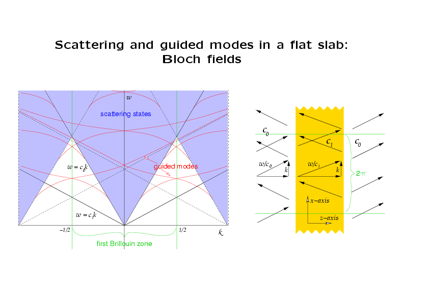
Let us now impose an artificial period of 2π in the x-direction and
write each Helmholtz field u(x,z) = v(z)eiKx as a
function w(x,z) that is periodic in x, times eikx, where the "Bloch wave
number" k lies in the first Brillouin zone [-1/2,1/2). Simply put
K = k + n, where n is an integer, to obtain
 u(x,z) = w(x,z)eikx
with
w(x,z)=v(z)einx.
u(x,z) = w(x,z)eikx
with
w(x,z)=v(z)einx.
Now, for
each k in [-1/2,1/2), there corresponds a sequence of guided
modes, whose frequencies are indicated by the red dispersion relations that have been "folded over"
into this zone. Those that fall on the blue zone corresponding to scattering
states can be thought of as frequencies of guided modes that are "embedded" in the
continuous spectrum of extended states.
For a fixed value of k, the frequencies of these guided modes
are eigenvalues embedded in the continuous spectrum of the Helmholtz
operator restricted to pseudo-periodic fields in the
infinite strip (0,2π)x(-∞,∞) with pseudo-periodic
factor e2πik. In the strip, the guided modes are square integrable.
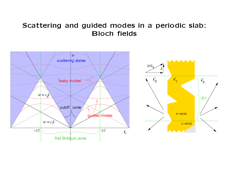
If we now impose a genuine periodicity upon the slab, the solutions
are no longer separable, and the periodic factor w(x,z) in the
Bloch fields attains all Fourier harmonics,
w(x,z) = Σn=-∞∞ vn(z)einx,
in other words, the Bloch wave number k is only determined up to an
additive integer, so we take it to lie in the first Brillouin
zone. To the left and right of the slab, the functions
vn(z) have the form
vn(z) = an eiηnz +
bn e-iηnz,
(with different coefficients to the left and right) in which
(ω/c)2 - ηn2 - (n+k)k
= 0 and ηn>0 if ηn2>0 and
iηn<0 if ηn2<0. We see that
there are a finite number of propagating Fourier harmonics (η is
real), and the rest are decaying, or evanescent, (η is imaginary). The
Fourier harmonics are also called the Bragg harmonics.
Since the Bloch fields typically contain all Fourier harmonics, those
with (k,ω) in the blue region above the cone
ω=c0k do not correspond to guided modes because at
least one of the harmonics (n=0) is propagating. Thus the
dispersion for guided modes disappears in that zone. Instead
there is a complex dispersion relation D(k,ω)=0. The real part of
ω is indicated by the dotted curves for real values of k. If the
imaginary part of ω is very small, these curves correspond to
"leaky modes" (we omit explanation of these here).
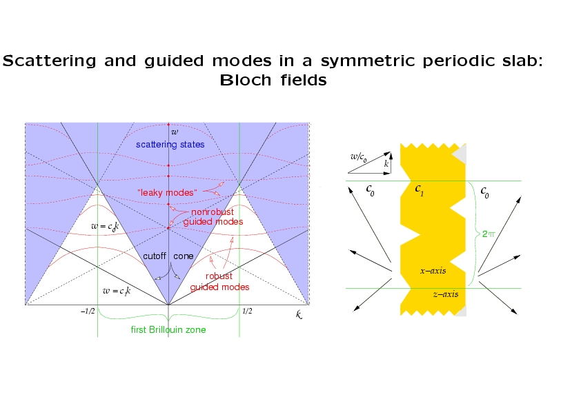
If the slab is symmetric about a horizontal line, then, for k=0,
solutions can be decomposed into
symmetric and antisymmetric parts. If, in addition, there is only one
propagating harmonic (meaning that (k,ω) is in the blue diamond shape bounded by
the cutoff cone and the dotted lines above it), then this
propagating harmonic, which is symmetric, vanishes for
antisymmetric solutions. Thus, if anitsymmetric solutions exist,
they will be guided modes. In fact, one can prove that they do
exist. They correspond to points on the complex dispersion
relation where ω happens to be real; their frequencies are indicated by
solid red dots on the graph. Since a perturbation of k
results in a small imaginary part of ω, the guide mode is seen to
disappear, and we call it nonrobust.
This is an instance
of the disppearance of an eigenvalue embedded in the continuous
spectrum of the Helmholtz operator with pseudo-periodic boundary
conditions in the strip (0,2π)x(-∞,∞), where the parameter of
perturbation is the pseudo-periodic factor e2πik.
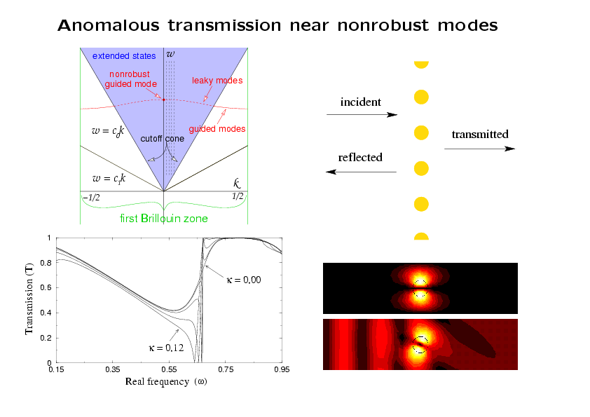
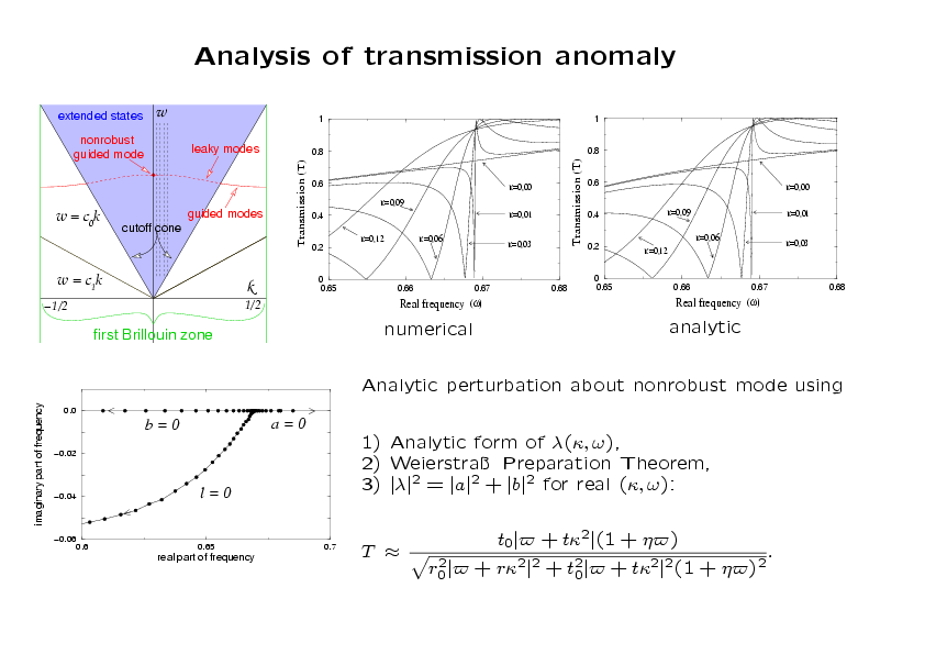
Numerical calculations of scattering by the yellow structure
consisting of an infinite row of rods (seen in cross-section)
demonstrate that a nonrobust guided mode produces anomalous
transmission behavior. The structure admits a nonrobust guided
mode at k = 0 and ω = ω0 ≈ 0.667 (actually a standing
mode because k=0). The transmission
coefficient has been calculated numerically for frequencies from
0.15 to 0.95 for several values of k between 0.0 and 0.12. These
intervals are shown by dotted vertical lines in the (k,ω)-plane,
and the transmission is plotted in the lower left (a zoomed-in plot is
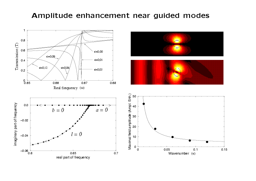
shown several panels below.) At k = 0, there is no anomaly.
In the lower right, one period of
the intensity of the guided mode is shown, and, below that, a
field scattered by an incident wave from the left at a small
nonzero value of k and a frequency near ω0. This
demonstrates the amplitude enhancement of fields due to resonant
scattering near the guided mode parameters.
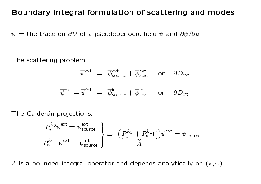
The scattering problem can be expressed in terms of values and normal derivative of the
source and total (or scattered) fields on the air-slab interface
in one period cell (in this case, over the boundary of one
circlular cross section of a rod). These boundary data are called the
traces of the fields. The total field trace
is decomposed in a unique way into the traces of the source and scattered field
exterior to the rod and in a (different) unique way into the
source and scattered field interior to the rod. These
decompositions are the images of the Calderón boundary projectors
corresponding to the Green functions for the exterior and interior
Helmholtz equations. The matrix Γ enforces matching conditions
across the interface (typically Γ=I or Γ=diag(1,ν), where η gives
the multiplicative jump in the normal derivative). The sum of the
two projectors is I (they are complementary) if the air and slab
have the same material properties. Otherwise, one shows the sum
is of the form B+C, where B is bounded and C is compact.
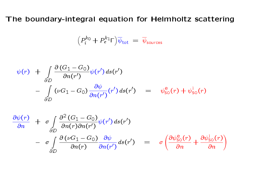
This is what the boundary-integral equations look like. The exterior (radiating)
and interior Green functions are denoted by G0 and G1.